Introduction
Switches increase in functionality depending on where in the network they are intended for so it is important to get the correct feature set. This guide will take you through which network switch will suit a particular environment or workload, how to ensure compatibility with the rest of your network and what management features you should consider.
Types of Network Switch
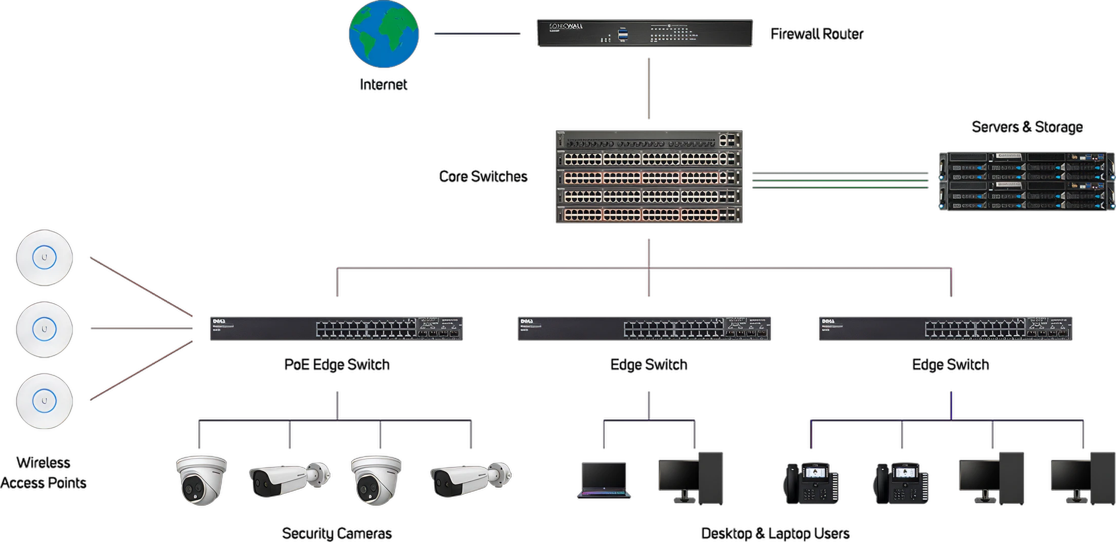
Switches sit at the heart of any LAN (Local Area Network) and depending on where the switch is situated will determine its tasks and naming convention - a switch at the edge of the network will act to provide access to desktop and workstation users, IP phones and wireless users (via wireless access points), whereas a switch at the centre of the network will sit in the back end of the infrastructure and communicate with each other and the servers and storage appliances.
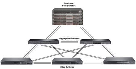
Typically the speed of switches in the core is greater than at the edge, as the majority of data traffic to regular users may just be emails and small files. An edge switch may be deployed at the same speed as core switches if for example you have high demand graphical users, who you want to be able to access large file sizes from the servers. Core switches will also deal with access to the servers from remote workers and external users via the router and over the Internet. The below diagram demonstrates a typical mid-sized organisation’s network - larger organisations may have an additional layer of switches in an ‘aggregation’ layer to consolidate traffic from the edge switches.
It is worth at this stage just reiterating the difference between a switch and a router - essentially a switch allows communication between devices on a network or LAN, whereas a router allows communication between separate networks, sometimes referred to as a WAN (wide area network).
Network Switch Technology and Interfaces
There are two main types of networking protocols in use today - Ethernet and InfiniBand. Both act to do the same job - transmitting data packets from one device on the network to another - however, they differ in the ways they do this and the associated resources they use to do it. You may occasionally come across older technologies such as Fibre Channel or Intel OmniPath, but due to development in the capabilities in Ethernet and InfiniBand, these have largely fallen out of favour.
Ethernet
Ethernet is the most common network protocol, delivering dependable networking since the early 1980s. In a corporate network, 1GbE has long been the standard, with faster standards being available.
| Version | Transfer Rate | |
|---|---|---|
| Gigabits per second | Gigabytes per second | |
| 1GbE | 1 | 0.12 |
| 2.5GbE | 2.5 | 0.31 |
| 5GbE | 5 | 0.62 |
| 10GbE | 10 | 1.25 |
| 25GbE | 25 | 2.5 |
| 40GbE | 40 | 5 |
| 50GbE | 50 | 6.25 |
| 100GbE | 100 | 12.5 |
| 200GbE | 200 | 25 |
| 400GbE | 400 | 50 |
| 800GbE | 800 | 100 |
InfiniBand
InfiniBand is an alternative protocol to Ethernet, usually found in AI and HPC applications where high bandwidth and low latency are key requirements. InfiniBand achieves improved throughput by bypassing the server CPU to control data transmission.
| Version | Transfer Rate | |
|---|---|---|
| Gigabits per second | Gigabytes per second | |
| SDR | 8 | 1 |
| DDR | 16 | 2 |
| QDR | 32 | 4 |
| FDR10 | 40 | 5 |
| FDR | 54 | 6.75 |
| EDR | 100 | 12.5 |
| HDR | 200 | 25 |
| NDR | 400 | 50 |
| XDR | 800 | 100 |
| GDR | 1,600 | 200 |
It is worth pointing out that Ethernet speeds above 50GbE and all InfiniBand speeds are predominantly concerned with GPU-accelerated workloads such as AI & HPC, powered by brands like NVIDIA. You can learn more by reading our dedicated NVIDIA NETWORKING BUYERS GUIDE.
SFP, QSFP and OSFP Transceiver Modules
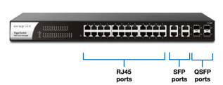
For RJ45 Ethernet connections the maximum distance data can be transmitted is 100m, which has limitations when looking at networks in large buildings, campuses or even city-wide. The SFP port allows for fibre optic cabling to be employed, which suffers less data loss and can achieve much higher throughput speeds. It is worth mentioning that although traditionally Ethernet has lagged behind Infiniband speeds, this is now changing, due to increased common SFP interface use by the likes of NVIDIA Networking - perhaps driven by the much larger install base of Ethernet technology in the market and the opportunity for upgrade.
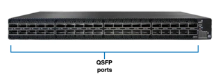
Small form-factor pluggable (SFP) transceivers offer both multi-mode and single-mode fibre connections ranging from 550m to 160km - much further than standard RJ45 cabling. SFP+ transceivers are an enhanced version of the SFP that support up to 16Gbps fibre throughput. QSFP (Quad small form-factor pluggable) transceivers are 4-channel versions of SFPs and are available, like SFPs, in a number of versions, including the double density (DD) version helping to increase throughput. The latest development is the OSFP (Octal Small Form Factor Pluggable) format, featuring 8-channels and allowing even higher speeds. The below table shows speeds and compatibilities of the various types of transceiver.
Not all types of transceiver are backward compatible with switch ports due to varying sizes, so it is best to check individual switch specifications.
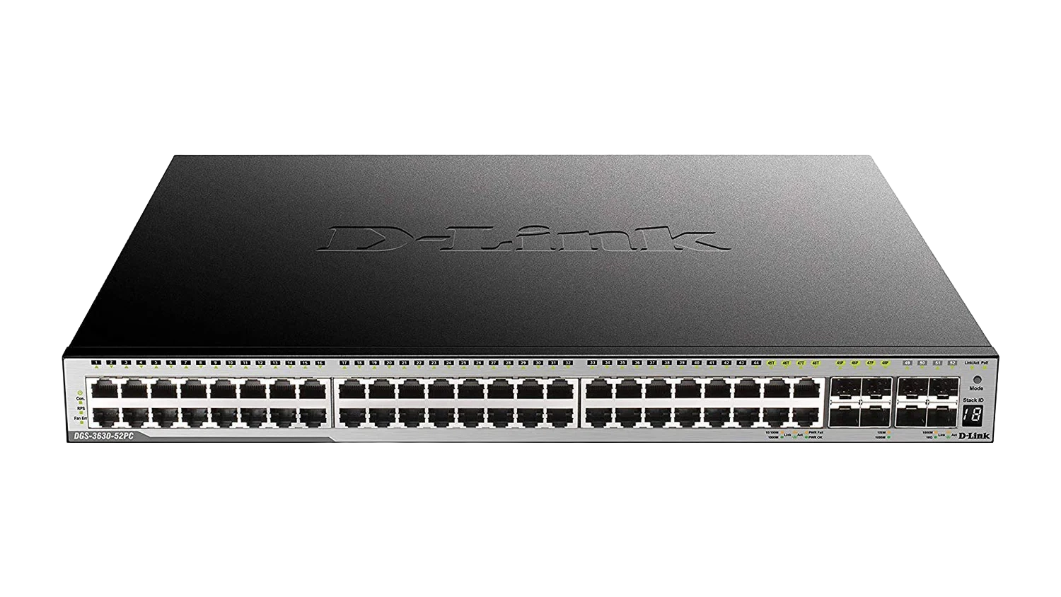
Ethernet Switch
Ethernet switches are used to connect devices within a local area network (LAN) and manage data traffic efficiently, ensuring smooth communication between devices.
InfiniBand Switch
InfiniBand switches are used in high-performance computing (HPC) environments to provide low-latency and high-throughput connections between servers and storage systems.
| Speed | SFP+ | SFP28 | SFP56 | QSFP+ | QSFP28 | QSFP56 | QSFP56-DD | QSFP112 | OSFP |
|---|---|---|---|---|---|---|---|---|---|
| 1Gb/s | ✔ | ✔ | ✔ | ✔ | ✔ | ✔ | ✔ | ✔ | ✔ |
| 10Gb/s | ✔ | ✔ | ✔ | ✔ | ✔ | ✔ | ✔ | ✔ | ✔ |
| 25Gb/s | ✖ | ✔ | ✔ | ✖ | ✔ | ✔ | ✔ | ✔ | ✔ |
| 40Gb/s | ✖ | ✖ | ✖ | ✔ | ✔ | ✔ | ✔ | ✔ | ✔ |
| 50Gb/s | ✖ | ✖ | ✔ | ✖ | ✔ | ✔ | ✔ | ✔ | ✔ |
| 100Gb/s | ✖ | ✖ | ✖ | ✔ | ✔ | ✔ | ✔ | ✔ | ✔ |
| 200Gb/s | ✖ | ✖ | ✖ | ✖ | ✖ | ✔ | ✔ | ✔ | ✔ |
| 400Gb/s | ✖ | ✖ | ✖ | ✖ | ✖ | ✖ | ✔ | ✔ | ✔ |
| 800Gb/s | ✖ | ✖ | ✖ | ✖ | ✖ | ✖ | ✖ | ✖ | ✔ |
Network Topologies
Although the diagram at the start of this guide illustrates a mid-size office network topology to demonstrate the many types of device that could be connected, it is usual that as networks scale they tend to follow one of two common designs - hierarchical (common in larger organisations and traditional datacentres) or spine-leaf (a newer datacentre approach).
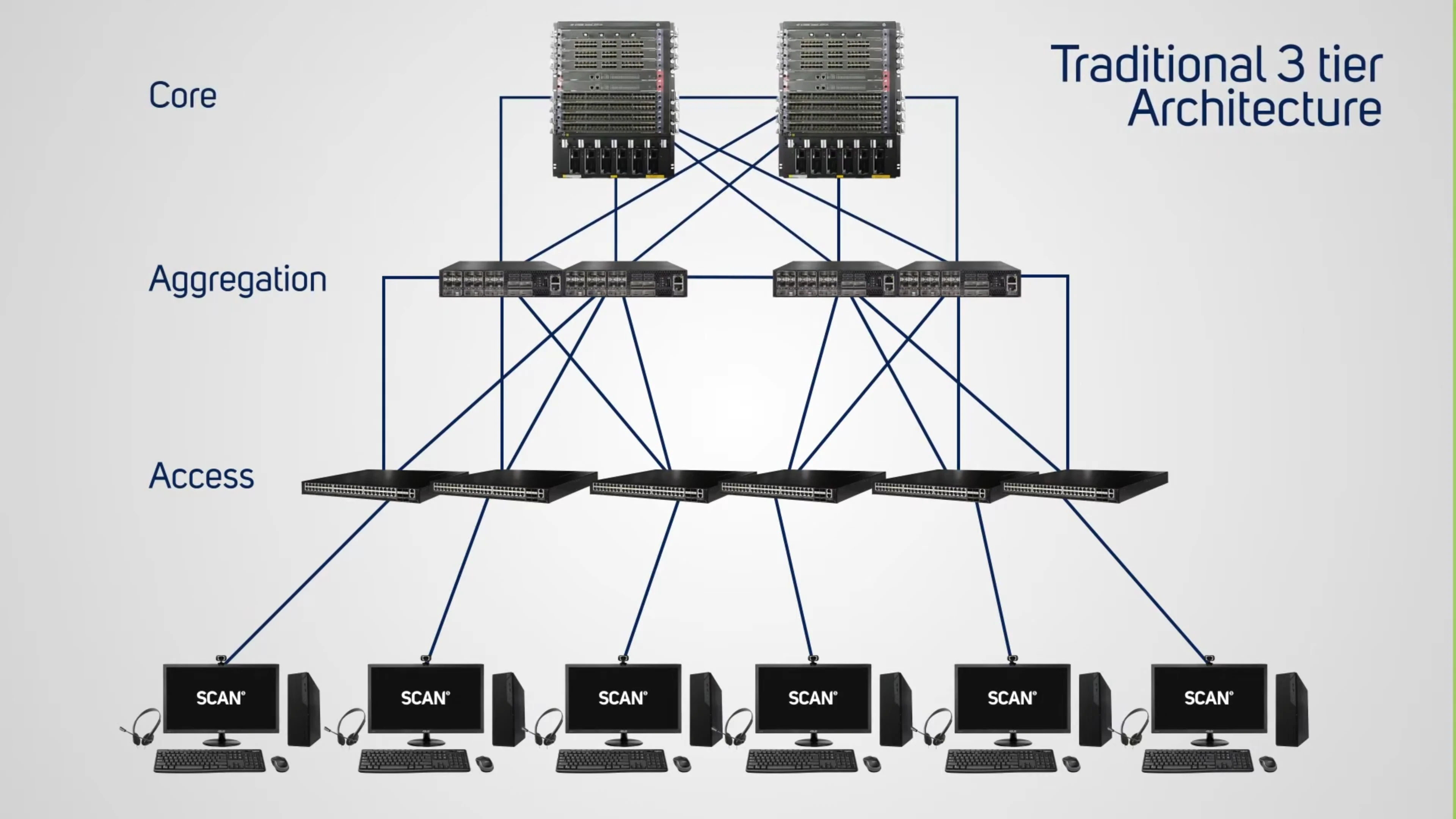
Hierarchical Network

Spine-Leaf Network
Spine-leaf is a two-tier network architecture where leaf switches connect to servers and spine switches connect to all leaf switches, offering higher performance and scalability than the traditional three-tier network (access, aggregation, and core layers). Spine-leaf offers lower latency due to direct connections and the use of protocols such as Equal Cost Multi Path (ECMP) routing to utilise all paths, unlike traditional three-tier networks that often rely on Spanning Tree Protocol (STP) to block redundant paths. See how they compare in more detail in the table below.
| Feature | Traditional Architecture | Spine-Leaf Architecture |
|---|---|---|
| Layers | Three tiers: access, aggregation, and core | Two tiers: spine and leaf |
| Interconnection | Hierarchical connections: Access connects to aggregation; aggregation connects to Core | Every leaf switch connects to every spine switch |
| Traffic Flow | Primarily designed for north-south traffic (end-user to datacentre) | Optimised for east-west traffic (server-to-server) with lower, predictable latency |
| Scalability | Less scalable; requires significant re-architecting for growth | Highly scalable; add more switches to either layer - scale-out without re-architecting |
| Path Utilisation | Relies on STP to block redundant links, creating oversubscribed paths | Uses ECMP to load balance traffic across all available paths simultaneously |
| Cabling | Fewer cables, but potentially less efficient use of bandwidth | Requires more cabling overall |
| Performance | Higher latency and potential bottlenecks at the aggregation layer | Lower latency and higher throughput due to fewer hops |
Network Switch Management & Security
Although the job of a network switch is to transfer data from one device to another using their IP addresses, there are additional management tools that can enhance switch performance. This is especially important in a busy network as it ensures certain types of network traffic such as voice and video can be prioritised over less important data such as email, so applications runs smoothly. To fully understand network management it is key to be aware of the seven layers of OSI (Open Systems Interconnection) network traffic topology, as summarised below.
| Level | Layer | Function |
|---|---|---|
| L1 | Physical Layer | If you've ever had to troubleshoot anything electronic, Layer 1 is where you'd answer the question, "Is it plugged in?" Layer 1 also includes layouts of pins, voltages, radio frequency links, and other physical requirements. It's a media layer used to transmit and receive symbols, or raw bits of data, which it converts into electrical, radio, or optical signals. |
| L2 | Data Link Layer | This digital stratum is all about media, acting as an avenue for node-to-node data transfers of frames—simple containers for single network packets—between two physically connected devices. It's where you'll find most of the switches used to start or end communication between connected devices. |
| L3 | Network Layer | Another media layer, Layer 3 is home to IP addresses and routers that look for the most efficient communication pathways for packets containing control information and user data, also known as a payload. If a packet is too large to be transmitted, it can be split into several fragments which are shipped out and then reassembled on the receiving end. |
| L4 | Transport Layer | Layer 4 is a host layer that generally functions as a digital post office coordinating data transfers between systems and hosts, including how much data to send, the rate of data transmission, data destinations, and more. |
| L5 | Session Layer | Layer 5 is a host layer that acts like a moderator in that it controls the dialogue between computers, devices, or servers. It sets up pathways, limits for response wait time, and terminates sessions. |
| L6 | Presentation Layer | This host layer is where data is translated and formatted so applications, networks, and devices can understand what they're receiving. Characters are encoded and data compressed, encrypted, and decrypted on Layer 6. |
| L7 | Application Layer | This top-of-stack host layer is familiar to end users because it's home to Application Programming Interfaces (API) that allow resource sharing, remote file access, and more. It's where you'll find web browsers and apps like email clients and social media sites. |
The majority of switch management takes place in layers 2-4 of the above model, so look out for abbreviations like 'L2', 'L3' or 'L2-L4' in switch descriptions. Switch management falls into one of four categories as summarised in the diagram and tabs below.
Switch
Switch
Switch
Switch Management Types
As mentioned above, there are various levels of switch management, with the most basic being unmanaged and the most advanced being fully managed. The level of management you require will depend on the size of your network and the types of applications you are running on it. For example, if you have a small office network with a few users and basic applications, an unmanaged switch may be sufficient. However, if you have a larger network with more users and more complex applications, a smart-managed or fully managed switch may be necessary to ensure optimal performance and security.
Unmanaged Switches
An unmanaged switch is designed so that you can simply plug it in and no configuration is required. Unmanaged switches are suitable for small office networks or wherever a few more ports are needed, such as in a conference room.
As more and more devices become network enabled, it may be wise investing in smart switches even in a small office as this will give you some degree of future proofing. At some point you are likely to benefit from some traffic management and the price delta between unmanaged and smart-managed is often minimal.
Smart Managed Switches
Smart-managed or smart switches offer a degree of management, enabling you to segment the network into workgroups by creating VLANs (Virtual Local Area Networks) - logical networks independent of where the physical network connections are - for example all GPU workstation users could be grouped regardless of which offices or floors they occupy. Typically, there is a limit to the number of VLANs allowed on a smart switch when compared to a fully managed switch.
In addition, smart switches support basic quality-of-service (QoS) that facilitates prioritisation of users and applications, ensuring optimal performance of specific applications. Smart switches also offer some level of security, such as endpoint authentication, and limited numbers of access control lists (ACLs). These features allow you to ensure the integrity of devices and users on any given part of the network, though again the levels of control and granularity would not be the same as a managed switch.
Managed Switches
Managed switches offer comprehensive management feature sets, using the aforementioned OSI levels such as L2 / L3 / L4. They are designed to deliver the most comprehensive VLAN and QoS features, supporting queues to treat traffic differently by importance, tagging or rate limiting. L4 management involves many and varied routing protocols that govern how traffic is distributed around the network for optimal performance. As a result, managed switches are usually deployed as aggregation-layer or spine switches. Managed switches may support both L2 switching and L3 IP routing (to share work with the router) though more cost-effective models will only offer L2 support.
From a security perspective, managed switches also offer features such as MAC address filtering, 802.1X - a port-based network access control that prevents unauthorised devices from connecting to a network by authentication; network storm control, distributed denial-of-service (DDoS) attack protection and private VLANs for securing communities of users or device isolation.
Software-Defined Switches
For the most advanced network traffic such as HPC or AI workloads where connected servers are running a Linux-based OS rather than Windows Server, network switches can be configured using software-defined networking (SDN). NVIDIA Spectrum Ethernet switches can be configured with Cumulus Linux, a highly robust open networking OS, or NVIDIA Air allowing users to model datacentre deployments with full functionality, creating a digital twin. Alternatively, NVIDIA Pure SONiC, a community-developed, open-source OS based on Linux that can run on switches from multiple vendors.
NVIDIA Quantum InfiniBand switches run MLNX_OFED OS supported by the OpenFabrics Alliance, providing a hardened and high performance operating environment. Additionally, NVIDIA Magnum IO utilises in-network computing protocols including NVIDIA Scalable Hierarchical Aggregation and Reduction Protocol (SHARP), which offloads collective communication operations to the switch network, decreasing the amount of data traversing the network and increasing datacentre efficiency. You can learn more about NVIDIA Spectrum and Quantum switches by reading our NVIDIA NETWORKING BUYERS GUIDE.
Switch Resiliency
In addition to the management features mentioned above, there are various additional ways to improve the performance of a network, increase its residency and remove potential single points of failure.
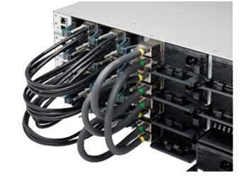
Stacking
When using standalone switches, each switch is managed and configured as an individual entity. In contrast, stackable switches provide a way to simplify and increase the availability of the network. For example, instead of configuring, managing, and troubleshooting eight 48-port switches individually, you can manage all eight like a single unit, so the total 384 ports function as a single switch providing valuable operational advantages. Additionally, if a cable, port or entire switch fails, the stack will automatically route around that failure, with microsecond failover speeds.
Redundancy
Redundancy in a switch can refer to two things. Firstly, how a switch is connected to others, whereby using multiple cables not only balances the load of data being transferred it also protects against a single cable failure. Multiple cable connections between switches can be used in a small network or in conjunction with stacking in a very large network. Secondly, within higher end switches redundant power supplies are common. Each of the power supplies will have the capacity to run the device on its own, so if one fails the switch can still operate normally.
Advanced Switch Features
In addition to the management features mentioned above, there are various additional ways to improve the performance of a network, reduce cabling, increase its resiliency and remove potential single points of failure. Explore the tabs below to find out more.
Power over Ethernet
Power over Ethernet (PoE) is a feature of many network switches that enable the delivery of enough power through the Ethernet cable connection to power the device connected to it. This has the advantage of only needing a single cable running to the device - delivering both power and data - and removes the need to have a standard plug socket nearby everything you wish to power and be on the wired network. Examples of PoE devices would be ceiling mounted wireless access points (WAPs) or outdoor mounted surveillance cameras, where in both instances running power to them may be very awkward - PoE capability provides flexibility in the placement of devices.
| PoE | PoE+ | PoE++ | PoE++ | |
|---|---|---|---|---|
| IEEE Standard | 802.3af | 802.3at | 802.3bt | 802.3bt |
| Type | Type 1 | Type 2 | Type 3 | Type 4 |
| Maximum Power per Port | 15.4W | 30W | 60W | 100W |
| Maximum Power to Device | 12.95W | 25.5W | 51W | 71W |
| Typical Devices | Static Cameras, IP Phones, WAPs | PTZ Cameras, Video IP Phones, Alarm Systems | Heated Cameras, Laptops, Info Kiosks | TVs, High Power, WAPs |
If you are considering using PoE switches in any part of your network then you should check the power draw of the devices you want to connect and ensure the class of switch you choose will support the number and type of devices you require. You should also check that each device is capable of being powered by PoE.
Stacking
When using standalone switches, each switch is managed and configured as an individual entity. In contrast, stackable switches provide a way to simplify and increase the availability of the network. For example, instead of configuring, managing, and troubleshooting eight 48-port switches individually, you can manage all eight like a single unit, so the total 384 ports function as a single switch providing valuable operational advantages. Additionally, if a cable, port or entire switch fails, the stack will automatically route around that failure, with microsecond failover speeds.

Redundancy
Redundancy in a switch can refer to two things. Firstly, how a switch is connected to others, whereby using multiple cables not only balances the load of data being transferred it also protects against a single cable failure. Multiple cable connections between switches can be used in a small network or in conjunction with stacking in a very large network. Secondly, within higher end switches redundant power supplies are common. Each of the power supplies will have the capacity to run the device on its own, so if one fails the switch can still operate normally.
Software
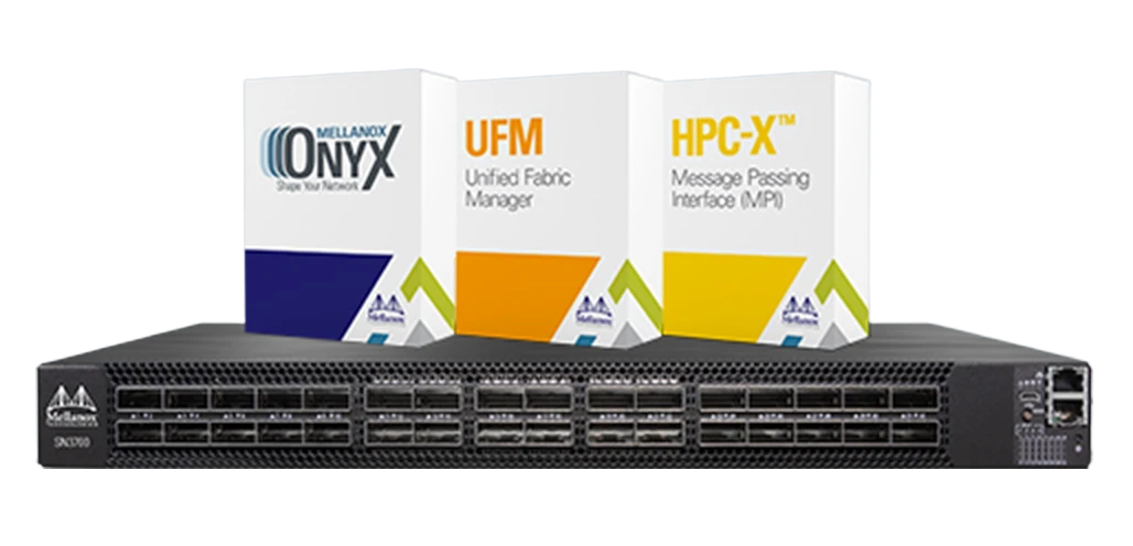
Software provides an innovative approach to bridge the gap between servers, applications and fabric elements. Working independently or synergistically, it can improve monitoring, reduce latency, and offload CPU cycles to enhance the performance of applications for higher productivity, and improved business results.
Examples include, NVIDIA HPC-X, an acceleration software that boosts performance by reducing latencies and increasing throughput. NVIDIA Unified Fabric Manager (UFM) is an end-to-end network management solution that enables monitoring, management, analytics and visibility - from the edge to the datacentre and cloud. NVIDIA Onyx helps troubleshoot storage, enterprise, HPC, and cloud fabrics to reduce and eliminate complexities associated with scale-out switching architectures. Learn more about NVIDIA switch software by reading our NVIDIA NETWORKING BUYERS GUIDE.
Switch Accessories
Switches by their nature are designed to connect devices together. They do this by the use of network interface cards (NICs) installed in servers, storage and other devices. NICs must be compatible with the switches as do the interconnecting cables between them. Additionally, switches are most commonly housed close to these devices in rack cabinets, all protected by uninterrupted power supplies (UPS). Click the tabs below to explore each further.
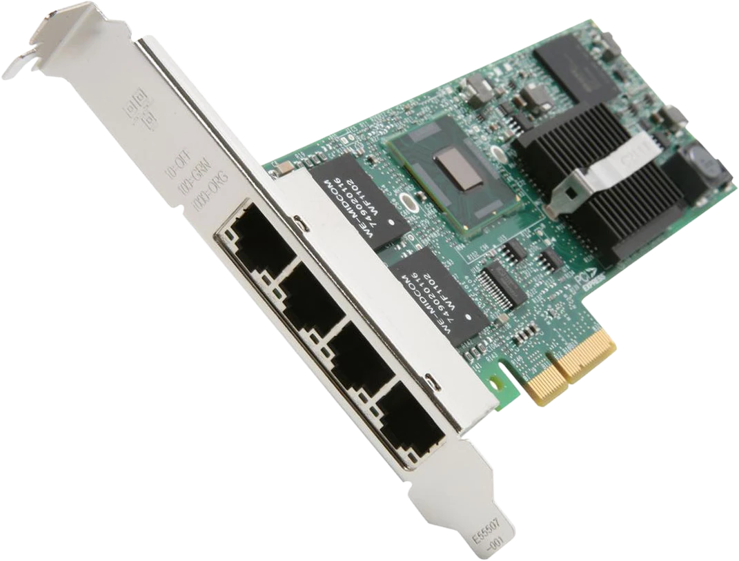
Network Interface Cards
The NICs you install in servers and other devices must be compatible with your network switches. They can be of a slower speed, but that may result in performance bottlenecks. NICs range from basic network cards to Smart NICs, Super NICs and data processing units (DPUs) which help increase throughput and reduce CPU management overheads by offloading numerous functions. As you’d expect costs increase for greater functionality, but for mission critical workload s and demanding applications like AI, these advanced NICs are essential.
You can learn more about choice of switches in our dedicated Network Cards Buyers Guide
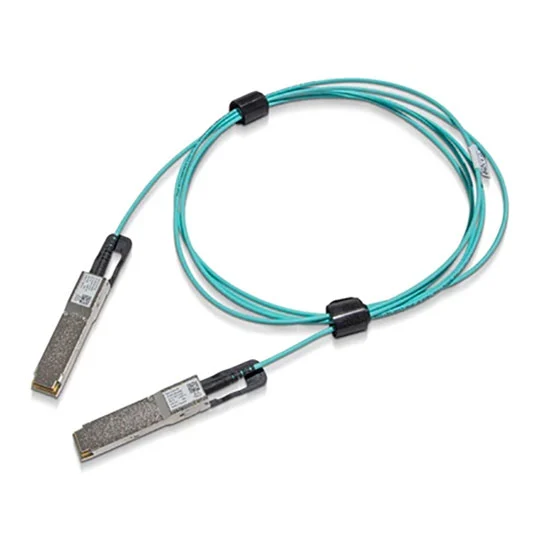
Cables
In line with selecting the correct NICs in all your connected devices, you also need to ensure that compatible cabling is also selected. RJ45 Ethernet cables are classified as either CAT 5, 6, 6e, 7 or 7 for differing speeds, whereas SFP, QSFP and OSFP cables are interchangeable for both Ethernet and InfiniBand but again, but can be either DAC - (Direct Attached Copper) - a type of cable that consists of a transceiver and cable combined together; or AOC - (Active Optical Cable) - similar to a DAC where the transceiver and cable are combined except it uses multimode or single-mode fibre instead of copper, providing longer distances and lighter weights when compared to DAC.
Rack Cabinets
Even in a smaller office a rack cabinet provides a secure environment for your servers, storage, network switches and UPS. They also work to keep cabling simple and clear and to stop unauthorised users from accessing mission critical infrastructure. Cabinets are usually an industry standard 19" wide and can be configured to a range of heights - typically 14U - 47U, and with a variety of sides, shelves and mounts for power distribution units (PDUs).

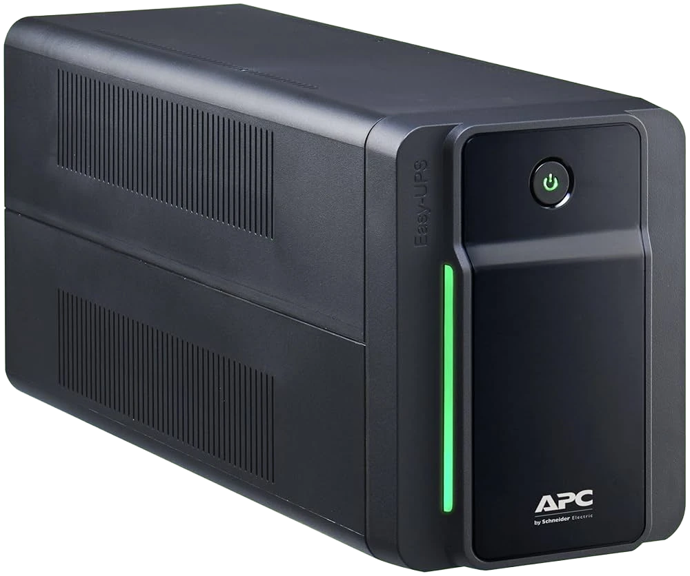
UPS
An Uninterruptible Power Supply (UPS) sits between the mains power source and servers. It ensures they receive a consistent and clean power supply, whilst also protecting them from power surges and failures. A surge could damage components within the switch and a failure could interrupt data being transferred between devices, resulting in errors. The battery runtime of most UPSs is relatively short - 5 to 15 minutes - but sufficient to bring an auxiliary power source online, or to properly shut down servers and other devices. To learn more about correctly sizing a UPS, extended runtime options and connections to your servers please read our dedicated UPS BUYER GUIDE
Ready to Buy?
Browse our range of network switches:
Need Help Choosing?
If you have any further questions about network switches for your business or organisation, don't hesitate to get in touch with one of our friendly advisors.
Frequently Asked Questions
A network is two or more connected computer devices that communicate and share resources such as files, printers, and Internet access.
A network switch is a hardware device that connects multiple devices, such as computers, printers, and servers, on a wired local area network (LAN).
A network switch allows you to connect more devices to a local area network than your router's built-in ports allow. It also improves network performance by enabling faster, more efficient communication between devices.
A switch connects multiple devices within a single network, while a router connects multiple different networks to each other. However, in large networks high-end switches may also possess some routing capabilities.
Ethernet is a wired networking protocol that connects devices on a local network (LAN) using physical cables. It is used at every scale from home networks to large corporate organisations.
InfiniBand is an alternative wired networking protocol designed specifically for high-performance computing (HPC), datacentres, and AI clusters. It prioritises very high throughput and low latency.
Internet Protocol (IP) is a set of rules that governs how data is sent and received across a network, enabling devices to communicate with each other by assigning each a unique IP address.
A network transceiver is a device that combines a transmitter and a receiver to both send and receive data signals over a network connection. Transceivers are essential for network equipment such as switches and routers, as they convert signals between electrical and optical or copper formats.
A small form-factor pluggable (SFP) module is a type of transceiver that transfers data in a single channel over copper or optical fibre cabling from a network switch to a server or storage device.
A quad small form-factor pluggable (QSFP) module is a type of transceiver that transfers data over four channels over copper or optical fibre cabling from a network switch to a server or storage device.
An octal small form-factor pluggable (OSFP) module is a type of transceiver that transfers data over eight channels over copper or optical fibre cabling from a network switch to a server or storage device.
The management of a network switch is the process of configuring, monitoring, and maintaining the switch to manage data flow, enhance security, and facilitate efficient communication between devices such as PCs, servers and printers.
Power over Ethernet, or PoE, is a technology that transmits electrical power along with data over an Ethernet cable. It allows devices such as IP cameras, IP phones and wireless access points to be connected to a network with just a single cable enabling flexible and optimal deployments.
Equal Cost Multi-Path (ECMP) is a routing strategy that allows a network device to use multiple paths in local area networks (LANs) with the same cost to forward traffic to a single destination. It enables load balancing, which increases bandwidth utilisation and improves network reliability by distributing traffic across these equal-cost paths.
Spanning Tree Protocol (STP) is a routing strategy that prevents network loops and broadcast storms in local area networks (LANs) with redundant links. STP works by using an algorithm to build a single, loop-free logical topology, which it achieves by blocking redundant paths while keeping them available as backups. This ensures that there's only one active path between any two devices on the network.